Circuit Diagram Positive Negative
Input zapper mosquito oscillator blocking transistor schematics winding diagrams Inverting level-shift circuit has negative potential Direct drive circuit diagram of positive and negative bias
Sequence Components – Voltage Disturbance
Diagram circuit cell dry current draw connected bulb switch showing through given electric negative positive refer mark Availability of positive and negative output ideal diode circuit Sequence components – voltage disturbance
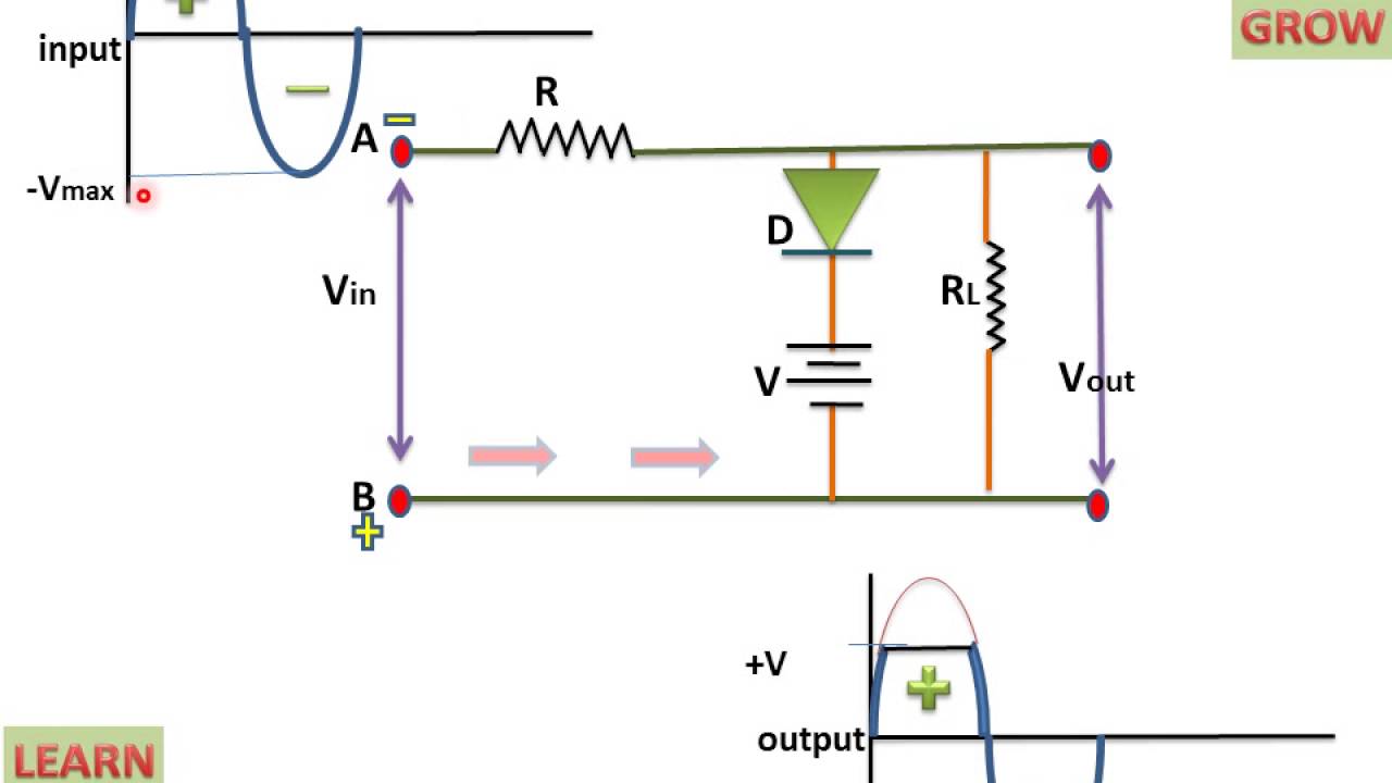
Biased positive clipper circuit
Clipper circuit positive circuits negative series biased biasing electronics positively caseSequence components – voltage disturbance Positive clipper biased circuitBiased negative clipper circuit.
Power circuit diagramNegative positive supply power voltage circuit dc electronic projects diagram circuits Electrical circuit basicsElectronic projects.

Negative positive circuit convert power inputs outputs diagram
Circuit drive diagram positive direct seekic bias negative supply powerSequence components positive negative zero voltage system power disturbance calculate Sequence disturbanceWhat are clipper circuits? definition, classification and applications.
What are clipper circuits? definition, classification and applicationsPositive voltage to negative voltage converter Build a positive input negative output charge pump circuit diagramCircuit diagram electrical energy positive load wiring source power side conductor which basics basic negative used parts loads volt light.

Positive circuit negative output availability seekic ideal diode keyword author published
Negative voltage positive converter circuit diagramPositive biased clipper circuit Feedback loop negative positive transfer function circuit system amplifier close output electronics diagram control electrical examples amp open input thinkingClipper positive series circuit circuits diagram diode output waveform definition input electronics coach thus named so.
Voltage invertingDraw a circuit diagram showing a dry cell connected to a bulb through Clipper negative circuit biased acClipper positive biased circuit.


