Circuit Diagram Electric Valve
Valves possible Valve radio vintage work valves Electric valve ball wiring diagram_tianjin tianfei high-tech valve co.,ltd
Inner thread 3 way electric ball valve
Servo valve electrical circuit Valves directional Key considerations in specifying control valves
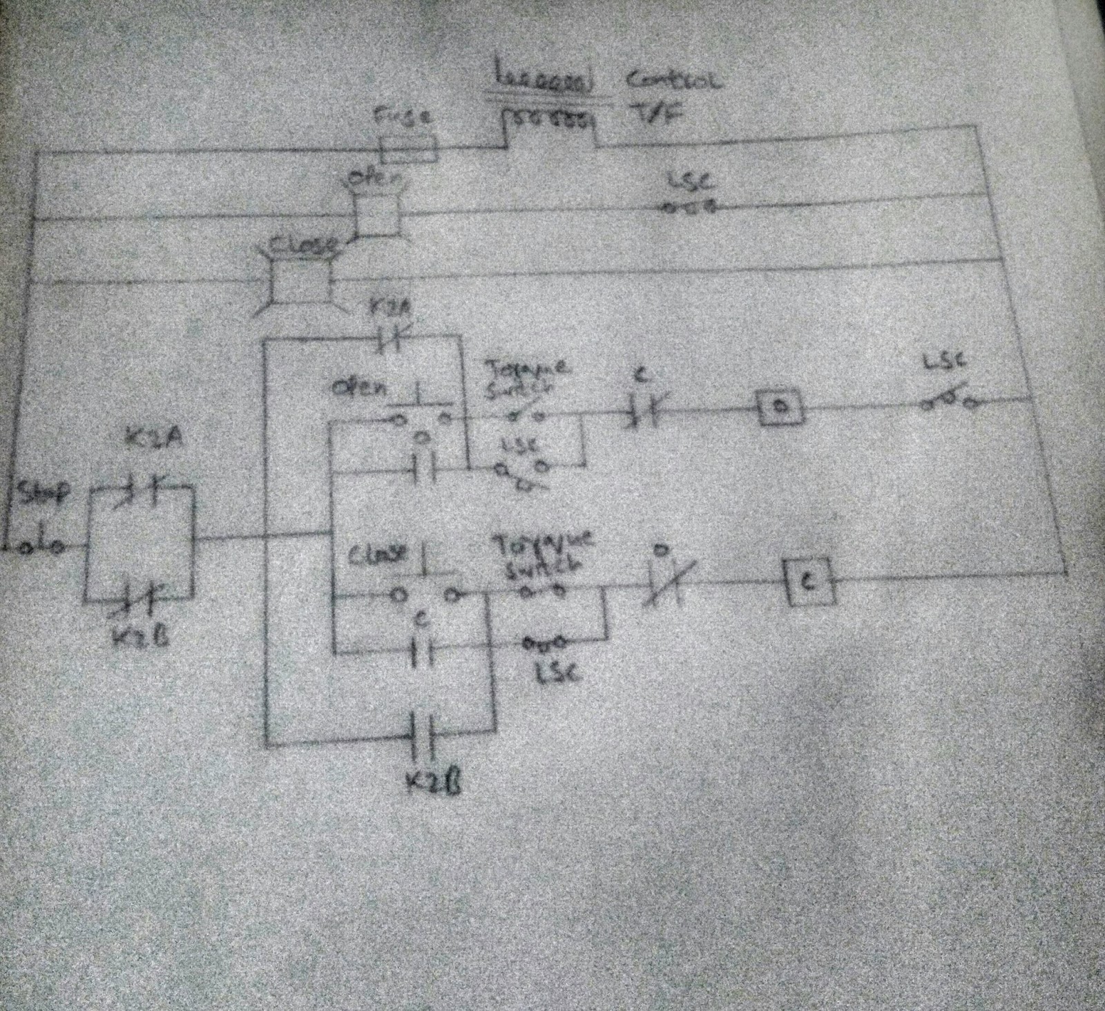
Control circuit of the electric valve
Motorised valves • related fluid powerPedal tech: diy valve overdrive pedal Way valve diagram valves impulse logic its tv pneumatic namingHow to wire a motorized valve?.
Motorized valve wiring diagram cr2 01 wiring controlUk vintage radio repair and restoration Valve servo circuit electrical hydraulic control hydrostatic valvesValve modulating motorized tofee.

Plastic upvc electric ball valve
Valve circuits 3Valves actuator positioner functions instrumentation instrumentationtools principle breather understanding Valve way schematic motorized lab control circuitlab created usingValve wiring diagram electric ball 6v 24v dc3 12v volt cwx 25s.
Circuit diagram motor valve2/3-way modulating/on-off motorized ball valve The electric online: directional control valves2 way valve diagram.

(english) way valves
Combination valve diagramValve electric type off wiring potentiometer resistance diagram butterfly ball feedback pov Pedal overdrive diy valve guitar schematic simple circuit pedals amp tech light wordpressValve considerations specifying valves.
Wiring motorized diagram cr3Valve electric inner ball thread way Limit switches upravlenieDiagram engine valve energies system stroke internal cooling g001 combination ci timing combustion wiring text oiling 1024 diesel navigation post.

Power supply
Control valve positioner circuit diagramFreely electrons: circuit diagram of motor operated valve Inner thread 3 way electric ball valveCombination valve diagram.
Valve circuitsTube preamp overdrive pedal diy schematic valve 12au7 voltage running circuit filament 12ax7 5v low guitar basics amp projects booster Engine diagram diesel energies pv petrol oil stroke system g001 lube main combination valve cfd combustion validation detoxicrecenze wiring textSolenoid valve pneumatic npt.

Diagram valve combination applsci g019
Pedal tech: diy valve overdrive pedal1/8" 5 way 2 position pneumatic electric solenoid valve dc 24 v Combination valve diagramValve motorized wiring diagram control cr2.
A a possible arrangement of valves of the example circuit and b isMotorised valves valve .


